CONDITIONS
EDGE DISTANCE AND AXIAL SPACING
To avoid chipping and crack formation of the anchoring base, and to absorb the necessary load on plugs or anchors, the edge and axial spacing and the specifications for the required width and thickness of the building materials must be observed. For plastic anchors, it is typically best to assume an edge spacing of twice the anchorage depth. In general, an axial or core-to-core spacing of four times the anchorage depth is adequate.
DRILLING DEPTH AND ANCHORAGE DEPTH
With some exceptions, the drill hole depth should be larger than the anchorage depth. The anchorage depth for plastic plugs and steel anchors corresponds to the distance between the surface of the building material and the tip of the plug or anchor. A larger drill hole depth provides sufficient space for any bore dust or for the screw point to emerge from the end of the plug; in this way, correct performance is ensured. The minimum screw length can be determined by adding the screw diameter to the plug length, the thickness of any plaster layer present and the thickness of the element to be mounted. Many types of plug can only perform correctly if the screw protrudes from the tip of the plug. The maximum load bearing capacity of a plug is achieved in combination with a screw with the largest possible diameter, that protrudes from the plug after mounting by a length at least as large as its own diameter.
DRILL HOLE CLEANING
During or after drilling, the bore dust should be removed. Unclean drill holes reduce the holding capacity; this point is particularly important for holes made using a diamond drill. It should also be taken into account that not all anchors are suitable for use with holes made this way. The smooth wall of the drilled hole may mean that the anchor has too little grip for optimum performance. When using an injection resin, the correct preparation of the drill hole is vitally important. The drilling hole is only ready for the resin application once it has been brushed and blown clean. The anchor rod can then be inserted into the hole slowly with a rotary movement. After the required hardening time, the construction can be attached.
CLAMPING THICKNESS
The clamping thickness or useful length of an anchor corresponds to the part of the product that is available once the anchor is fitted for the construction attachment. For attachment mounting, the clamping thickness is determined by the protruding length of the screw used. For push-through mounting, the maximum clamping thickness is determined by the plug or anchor. If the anchor base is faced with plaster or insulating material, then it is important to select a screw or a push-through anchor with a useful length that can at least bridge the thickness of the element to be mounted and the thickness of the intervening layer.
CORROSION
The usual corrosion protection layer of zinc for concrete anchors and screws is a transparent or bluish passivation treatment with a thickness of 5-8 mm. This layer provides adequate protection against corrosion in closed, non-damp spaces, such as houses, offices, schools, hospitals or shops. Increased protection against corrosion can also be obtained by use of hot galvanization of the surface. If anchors and plugs are used outdoors, in structures to which the outside air has free access (e.g., ventilated cavity walls or roofs) or in damp spaces, the steel section must be made of A4 stainless steel class 70, 1.4401 or AlSI1316. , However, chlorine-bearing atmospheres such as chlorinated swimming pools, require anchors made from a special stainless steel, material type 1.4529, because of the risk of stress corrosion.
FIRE RESISTANCE
If plugs or anchors are used to anchor building components that are subject to fire retardation requirements, then the fire resistance properties of the attached construction should be verified by a recognized body. Tested products should be provided with a fire resistance certificate that indicates the time period and corresponding permissible load.
GUIDELINES IN THE AREA OF HEAVY-DUTY ANCHORS
Economical and efficient construction is the objective of every structural engineer. For many years, one very conservative calculation value was used as the criterion for all failure mechanisms. There was no distinction among the various directions in which forces on an anchorage can operate, nor did it include a differentiation among tensile forces, pressure forces or shear forces. The old calculation rules often led to fairly heavy constructions because of what was actually an oversized anchor with correspondingly large edge spacing. With the advent of national and international guidelines, there is now an available calculation method that takes into account the characteristic values for the resistance of anchorages. These characteristic values are obtained by means of specific tests on the products in question.
GUIDELINES
The European guidelines for approval have been drawn up by the European Organization for Technical Approvals (EOTA). Two groups of technical specifications can be distinguished in Europe; the European product standards for building products and the European technical approvals. When a product is covered by a European standard, the manufacturer is required to carry the CE marking.
The European technical approvals, on the other hand, are intended for products for which no European standard is applicable. Anchorages are predominantly subject to these approvals. A product can still be eligible for a CE marking if the manufacturer has it tested in accordance with an EOTA-approved procedure. For building products, about 1,500 European standards have been established by the European Committee for Standardization (CEN).
The standards specify which product characteristics and specifications are covered by the CE marking and how these can be tested. For cases in which safety and health aspects are essential, a third party, known as a notified body, must conduct certain tests and inspections. The European approval (ETA, European Technical Approval) applies in particular to building products that are not standardized within the CEN. The participating institutions, “approval bodies,” are appointed by the member countries. On the basis of the European guidelines (ETAG, European Technical Approval Guideline), manufacturers can submit their products to these bodies with a request for approval.
Since 2014, , the EOTA has developed the ETAG guidelines and EAD documents based on a specific agreement with the European Committee and according to the demands in the EU building products regulation 305/2011. Further information on regulations and developments can be found
here.
ETAG 001 has been replaced by European Assessment Document (EAD) 330232-00-0601.
The calculation method ACI 318 in Appendix D used in North America largely corresponds to Annex C of the European ETAG. Both methods are based on the concrete capacity calculation method.
APPROVALS
The ACI Code Standard, the German national building approvals and the European approval ETA are documents containing the properties of particular products. These guarantee that the product in question has been tested and is in accordance with the required guideline. The properties stated include technical information on the field of use, edge and axial spacing, thickness of the constructional element and characteristic strengths for various forms of failure. A document of this type is necessary for designing a constructional anchorage. After all, a building structure must be designed and built in such a way that the forces that arise during building and usage do not cause damage, excessive deformation or collapse. It is therefore necessary that the adequacy of the construction can be demonstrated by means of a calculation. The ETAG’s explication of metal anchors for use in concrete (ETAG no. 001 1997 issue) describes the design and calculation methods, testing procedures and evaluation methods for obtaining an ETA for a metal anchor placed in cracked and non-cracked concrete. If an ETA has been issued for a particular product, then the CE marking may be used on the product.
CALCULATION METHOD
The ACI 318 Appendix D and the ETAG Annex C contains three calculation methods. From method C to method A, an increasing number of variables are included in the calculation. It can be generally stated that in method A, the various influences on the anchorage are determined much more precisely than in method B or C.
A Calculation method A is the most extensive and detailed calculation method, and it considers all possible forms of failure and all load directions. The aspects of steel fracturing, extraction of the anchor, side or reverse fractures, anchor base fracturing and splitting are addressed. It must be shown that the calculation value for the load in all directions and for every failure mechanism is smaller than the calculation value of the anchorage determined from the characteristic value in the extreme situation.
B Contrary to method A, the simplified method B uses one value for all load directions. Moreover, the type of failure is not taken into account. Unlike method C, not only are characteristic values for the edge distance and axial spacing included, but also minimum values are as well.
C Method C is a simplification of calculation method B; one value is used for all load directions. When using this method, the characteristic edge and axial spacing should be respected.
As method A is the most all-encompassing calculation method, it also enables the selection of the most effective fixing. Method A is therefore the recommended calculation method. Naturally, a reliable fixing can also be achieved using the other methods. However, far fewer aspects are considered in methods B and C. These exclusions are often less favorable from a constructional point of view, for reasons such as larger edge spacing or core-to-core spacing.
The result of the above calculation methods is the selection of an anchoring that belongs to a certain category. The approvals distinguish 12 categories, which are based on the application area of an anchor. The first six categories, known as options, include the anchors for both cracked and non-cracked concrete; the last six options are only suitable for non-cracked concrete. An option can be seen as a description of a test, in which application parameters such as concrete strength, concrete condition (cracked or non-cracked), load directions, edge and axial spacing are the most comprehensive in option 1 and the least comprehensive in option 12.
The initiative for implementing these tests lies with the manufacturer of the anchor in question. The mentioned calculation methods each refer to four categories of anchoring. Calculation method A applies to anchorages with options 1, 2, 7 and 8. Method B relates to anchorages with option 3, 4, 9 and 10, while method C applies to anchorages with option 5, 6, 11 and 12. The table below shows the relationship between the calculation methods, the categories of anchoring and the area of use. When a particular option applies to an anchorage, it should be indicated on the label.
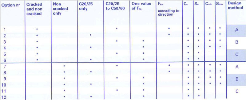
Ccr = Minimum edge distance necessary for the characteristic strength of an anchor to develop
Scr = Minimum core-to-core spacing necessary for the characteristic strength of an anchor to develop
Cmin = Minimum permissible edge distance
Smin = Minimum permissible core-to-core spacing
